Milling Process and Quality Analysis of Mold in Milling Teaching (2)
two. Milling of the die
   Figure A-2 is a concave mold matched with Figure A-1. It is required to ensure that the clearance with the punch is not more than 0.25mm. The workpiece drawing shown in Figure A-2 is taken as an example to introduce the die milling step.
   1. High-speed milling of the hexahedron to the pattern on the end mill with end mills requires a grinding allowance of 0.3 mm on the two base faces A, B and C, and a hexahedron with a diameter of 136.5 mm, a width of 70 mm and a height of 55 mm. Grinding the A, B and C faces on the surface grinder to the pattern requirements.
   2. Milling cavity
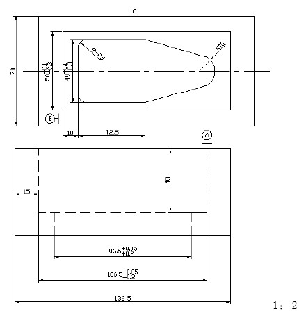
Figure A-2 Die Milling
(1) Scribing, according to the requirements of Figure A-2, draw the outline of the workpiece and mark the A, B, and C faces.
1 Draw a symmetrical center line on the A and B sides, and draw a line contour of 106.5×50mm on the A side; centered on the intersection of the four corners, draw the size line of the φ6mm hole and punch the eye.
2 Draw 86.5×40 concave cavity contour line on the B surface, and draw two arc lines and diagonal lines of R5 and R10 at the same time to make a punch.
Figure A—2—1
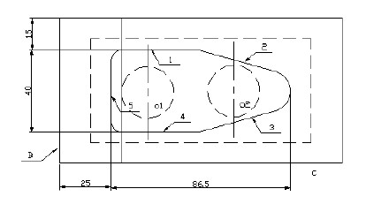
Figure A—2—2
(2) Milling steps:
1 Mount the machine on the end mill with a vise and clamp the workpiece A face up in the vise. Find and make the A side parallel to the table within 0.02mm. The parallelism between the C-plane and the longitudinal feed direction is within 0.02 mm, and the B-plane perpendicularity is guaranteed to be within 0.02 mm.
2 Drill holes at the four corners with a φ6mm drill bit to a depth of 40mm. The drill hole O1 and O2 (see Figure A-2-1) should not touch the edge of the cavity.
3 Use φ25~30mm large spiral angle end mill to roughen the cavity and control the milling depth.
The amount of finishing milling is 2 to 3 mm. The processing sequence is shown in Figure A-2.
4 Finishing the cavity to 106.5×50mm, the bottom corner R4 arc surface.
5 Rough and fine milling of the cavity contour of 86.5×40mm with a depth of 15mm. The milling sequence is shown in Figure A-2-2, milling the R10 arc surface and the two R5 arc surfaces.
When cutting the die, it should be matched with the punch shown in Figure A-1, and the matching clearance between the two can be no more than 0.25mm.
3. Detect the workpiece and use the vernier caliper, angle ruler, R gauge or template to detect each size according to the pattern.
Previous page next page
Electric Winches,Permanent Motor Electric Winches,Electric Winch On Winch Bar,Wound Recovery Electric Winch
JINHUA RUNYE TECH. CO.,LTD , https://www.cnirunwinch.com