Trouble shooting
Fault phenomenon
The Y-axis reading is normal and the X-axis can read, but there is an error. After repeated trials, there is an error of 1 to 5 mm for every 30 to 50 mm. The test method is: at some point, the workbench first clears the X-axis data, moves the machine table, starts counting in the X-axis direction, counts to 30~50mm, and then returns the workbench to the original position. At this time, The data on the counter cannot be returned to zero, but it varies from 1 to 5 mm, and the error of each test is different.
The X-axis and Y-axis read heads are swapped and tested in the same way as above, and the result is still an error in the X-axis reading head. Therefore, it is determined that the X-axis readhead is faulty.
2. Troubleshooting process
The waveform output from the readout head is measured by an oscilloscope. The phase A (header signal output line, pin 6 of the 9-pin plug) has a normal waveform, and the output waveform is a square wave signal. The reading head moves at a different speed, and the width of the square wave pulse is different. The faster the speed, the higher the frequency of the output square wave signal. When measuring the waveform of phase B (reader signal output line, pin 8 of 9-pin plug), the signal waveform is abnormal. Only when the reading head moves to the vicinity of one end of the grating ruler, there is a signal, but the output square wave has a short time and a high time is long, and in other parts, almost no low-level waveform is seen, which looks like High level.
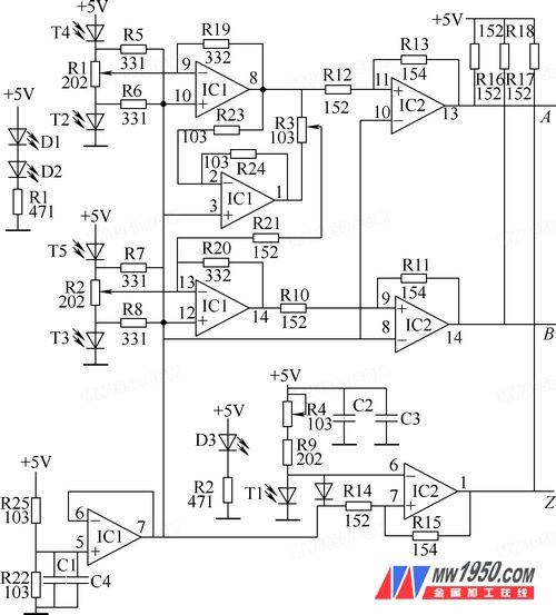
From the figure, the signal of phase B is related to signal source T3, T5 and potentiometer R2. It is also related to the output signal of phase A and potentiometer R3. Then adjust the potentiometer R3 and measure the output waveform of phase B. Then the waveform is normal, and it is loaded on the machine tool . If it is tested, the count is not normal. Using the dual trace oscilloscope to simultaneously observe the waveforms of phase A and phase B, it is found that the phase B output waveform is normal, but the waveform is opposite to phase A, ie. Therefore, the potentiometer R3 is restored to its original position. Then re-analyze the circuit principle, in order to prevent the influence of the A-phase signal on the B-phase, cut off the path connecting the A-phase and the B-phase, and solder the resistor R21. From the source of the B-phase signal, the voltmeter (the voltage of the multimeter 2.5V) is connected between the anode and the cathode of the photodiode T2, T3, T4, T5, change the sensitization of the photodiode, observe the change of voltage, and find When the light changes are the same, the voltages across T2 and T4 vary greatly, and each has a change of about 0.6V, while the voltage across T3 and T5 changes little, about 0.3V, which is suspected to be caused by aging of the photodiode. I want to change it, but I can't buy it in a short time. I can only solve it by adjusting the parameters of the circuit components. By analyzing the op amp corresponding to pins 6-7 of IC1, it is a voltage follower, which provides a reference voltage of about 2.5V for other op amps, so adjust the potentiometer R2 while ensuring that the T3 and T5 photodiodes receive the same light. Let the potential of pin 13 of IC1 be as close as possible to the reference voltage of pin 12 of IC1. After the adjustment is almost completed, connect the oscilloscope to the B-phase output to move the read head, observe the B-phase output waveform, and have a square wave output. However, the high level and the low level are asymmetrical, so adjust the potential while observing the waveform. R2 makes the high and low waveforms symmetrical. Then solder the R21 back to the original place. The waveforms of the A phase and the B phase are observed simultaneously by the dual trace oscilloscope, and the two phase waveforms are normal, and the waveform phases of the A phase and the B phase are 90° out of phase. The scale is mounted on the machine and the measurement data is restored.

Schematic
3. Conclusion
There are many types of numerical control detection systems. The structure of the KA-300B grating scale is introduced here, and the fault phenomenon and maintenance process of the grating scale are described in detail. After the overhaul, it takes a long time to work well.
Elevators, slips, wellhead tools for oil drilling Casing elevator slips, tubing elevator slips, sucker rod elevator slips, drill collar elevator slips, drill pipe elevator slips. The hydraulic elevator is a split type elevator. Taper drill pipe, drill collar, casing and tubing can be suspended by replacing the inner lining. The hydraulic control system is more convenient to operate, which can effectively reduce the labor intensity of workers and improve work efficiency. Can realize remote control, safe and reliable to use. The elevator is designed and manufactured according to API Spec 8C "Drilling and Oil Production Lifting Equipment". Slips are designed and manufactured according to API Spec 7K requirements The company has developed a wide range of oil drilling and production wellhead mechanized tools, complete specifications, various slips, elevators, and more than 100 series of product structure specifications, and sales cover major oil fields across the country, as well as Europe, the Middle East, Central Asia, Southeast Asia and other regions.
Elevators And Slips,Casing elevator slips, tubing elevator slips, sucker rod elevator slips, drill collar elevator slips
Rugao Yaou Import & Export Trade Co., Ltd , https://www.ntyaous.com