Suitable for fasteners, understand complex machining drawings!
Do you understand the various drawings of the various processing procedures that come in and out of the processing site? The processing plan provided by the customer, there is a question about the size of the wood? This small series brings you a different kind of classic - dimensioning knowledge in mechanical design! No longer have to worry about not understanding the drawings!
1, the size of the common structure noteCommon hole size injection method (blind hole, threaded hole, counterbore, flat hole); chamfer size injection method.
Blind hole
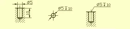
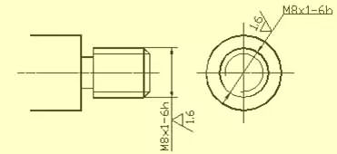
Threaded hole
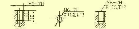
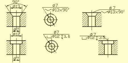
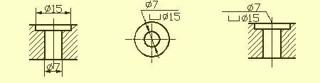
Counterbore
锪平å”
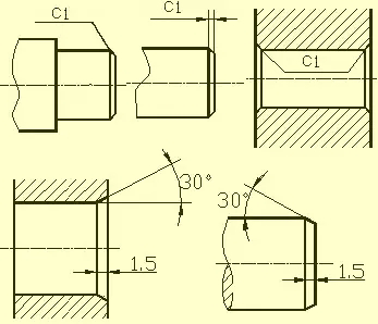
Chamfer
2. Machining structure on the part
退 Retreat and grinding wheel overtravel
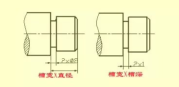
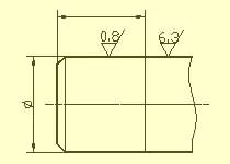
In the process of cutting parts, in order to facilitate the exit of the tool and to ensure that the contact surface of the relevant parts is tight when assembling, the undercut groove or the grinding wheel overrunning groove should be pre-machined at the step of the surface to be machined.
The size of the undercut when turning the outer circle can be generally marked by the "groove width x diameter" or "groove width x groove depth". Grinding wheel overrunning groove when grinding the outer circle or grinding the outer and end faces.
é’»å” Drilling structure
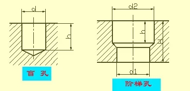
A blind hole drilled with a drill has a taper angle of 120° at the bottom, and the depth of the bore refers to the depth of the cylindrical portion, excluding the taper. At the transition of the stepped borehole, there is also a 120° cone with a taper angle, drawing and dimensioning.
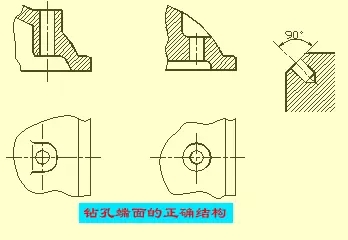
When drilling with a drill bit, the drill axis is required to be perpendicular to the end face of the drilled hole as much as possible to ensure accurate drilling and avoid breakage of the drill bit. The correct structure of the three bore end faces.
凸 bosses and pits
The contact surface of the part with other parts is generally processed. In order to reduce the processing area and ensure good contact between the surface of the parts, bosses and pits are often designed on the casting. A bolt-supported support surface boss or a support surface pit; in order to reduce the machining area, a groove structure is formed.
3, common parts structure
è½´ Bushing parts
Such parts generally have parts such as shafts and bushings. When the view is expressed, by drawing a basic view and adding appropriate sections and dimensions, the main shape features and local structures can be expressed. In order to facilitate the drawing when processing, the axis is generally projected horizontally, and it is preferable to select the position where the axis is the side perpendicular.
When dimensioning a bushing-like part, its axis is often used as a radial dimension reference. Thus, Ф14 and Ф11 (see AA section) shown in the figure are taken out. This unifies the design requirements and the process reference during machining (the shaft parts are lapped against the center hole of the shaft when machining on the lathe). The reference in the length direction often uses important end faces, contact faces (bearing shoulders) or machined faces.
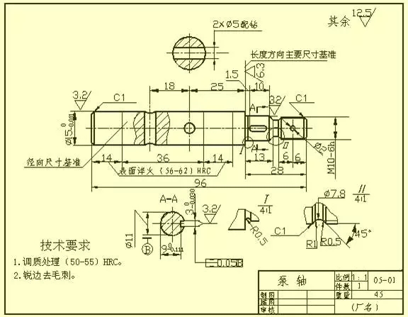
As shown in the figure, the right shoulder with a surface roughness of Ra6.3 is selected as the main dimension reference in the longitudinal direction, thereby injecting dimensions of 13, 28, 1.5, and 26.5; and then the right axis end is the length direction. The auxiliary base, thus marking the total length of the shaft 96.
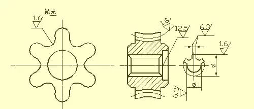
盘 Cover partsThe basic shape of such parts is a flat disk shape, generally having end caps, bonnets, gears and the like. Their main structure is generally a rotating body, usually with various shapes of flanges, uniformly round holes. And local structures such as ribs. In the view selection, the cross-sectional view of the symmetry plane or the rotary axis is generally selected as the main view, and other appropriate views (such as left view, right view or top view) are added to express the shape and uniform structure of the part. As shown in the figure, a left view is added to express a square flange with rounded corners and four evenly spaced through holes.
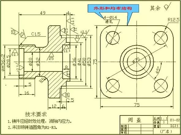
When dimensioning the parts of the disc cover, the axis passing through the shaft hole is usually selected as the radial dimension reference, and the main dimension reference in the length direction is often selected as the important end face.
â– Fork parts
Such parts generally have forks, connecting rods, bearings and other parts. Due to their variable processing position, the working position and shape characteristics are mainly considered when selecting the main view. For the selection of other views, two or more basic views are often required, and the partial structure of the part is expressed by an appropriate partial view, sectional view or the like. The view selection scheme shown in the footrest part drawing is refined and clear. For the expression of the width of the bearing and the rib, the right view is not necessary, and for the T-shaped rib, the profile is suitable.

When dimensioning a fork-like part, the symmetry plane of the mounting base or part is usually used as the dimensional reference. See the figure for the dimensioning method.
ç®± Box parts
In general, the shape and structure of such parts are more complex than the previous three types of parts, and the machining position changes more. Such parts generally have parts such as a valve body, a pump body, and a reducer case. When selecting the main view, the work position and shape features are mainly considered. When using other views, appropriate auxiliary views such as cross-section, section, partial view and oblique view should be used according to the actual situation to clearly express the internal and external structure of the part.
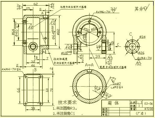
In terms of dimensioning, the axis required for design, the important mounting surface, the contact surface (or the working surface), the symmetry plane (width, length) of some main structures of the box are usually selected as the dimensional reference. For the part of the box that needs to be machined, it should be dimensioned as much as possible for processing and inspection requirements.
4, surface roughness
â– Concept of surface roughness
The microscopic geometry characteristic of the peaks and valleys with smaller spacing on the surface of the part is called surface roughness. This is mainly due to the tool marks left on the surface of the part and the plastic deformation of the surface metal during the cutting process when the part is machined.
The surface roughness of the part is also a technical indicator to evaluate the surface quality of the part. It affects the mating property, working precision, wear resistance, corrosion resistance, sealing and appearance of the part.
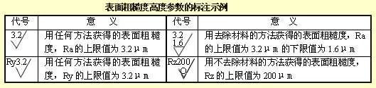
代 The code, symbol and label of the surface roughness
GB/T 131-1993 specifies the surface roughness code and its method of injection. The symbols on the drawings indicating the surface roughness of the parts are shown in the table below.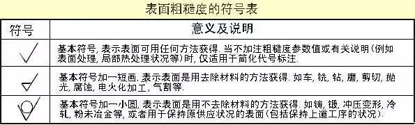
ä¸»è¦ Main evaluation parameters of surface roughness
The evaluation parameters of the surface roughness of the parts are:
1) Outline arithmetic mean deviation (Ra)
The arithmetic mean of the absolute value of the contour offset over the length of the sample. The value of Ra and the length of the sample l are shown in the table.

2) Maximum contour height (Rz)
The distance between the contour peak line and the bottom line of the contour peak over the length of the sample.
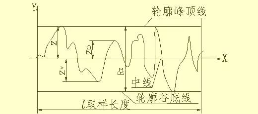
Note: The Ra parameter is preferred when using.
æ ‡æ³¨ Surface roughness marking requirements
1) Example of code numbering of surface roughness
When the surface roughness height parameters Ra, Rz, and Ry are numerically labeled in the code, except for the parameter code Ra, the corresponding parameter code Rz or Ry should be marked before the parameter value. The labeling example is shown in the table.
2) Surface roughness is marked in the surface roughness and the direction of the numbers and symbols
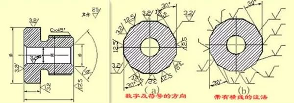
æ ‡æ³¨ Surface roughness symbol marking method on the pattern
1) The surface roughness generation number should generally be noted on the visible outline, the extension line or their extension line, and the tip of the symbol must point from the outside of the material to the surface.2) The direction of the numbers and symbols in the surface roughness code must be marked as specified.
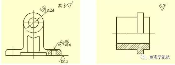
Example of labeling of surface roughness
On the same pattern, each surface is generally only marked with a generation (number) and as close as possible to the relevant dimension line. Labels can be drawn when the space is small or inconvenient to mark. When all surfaces of the part have the same surface roughness requirements, they can be uniformly marked in the upper right corner of the pattern. When most of the surface of the part has the same surface roughness requirement, the most used one can be used. Also note the top right corner of the drawing and add the words "rest". The surface roughness code (descriptive) number and explanatory text of the uniform label shall be 1.4 times the height of the pattern label.
The surface of the continuous surface on the part, the surface of the repeating elements (such as holes, teeth, grooves, etc.) and the same surface connected by a thin solid line, the surface roughness is only one time.
When there are different surface roughness requirements on the same surface, the thin line is used to draw the boundary line, and the corresponding surface roughness code and size are marked.
When the working surface of gears, threads, etc. is not drawn with a tooth (tooth) shape, the surface roughness is shown in the figure.

The working surface of the center hole, the working surface of the keyway, the chamfering, and the surface roughness code of the rounded corners can simplify the labeling.
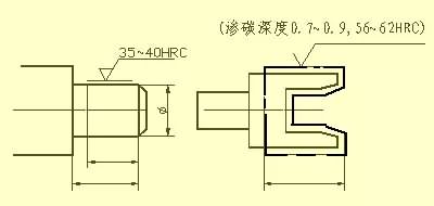
When the part needs to be partially heat treated or partially plated (coated), the range is drawn with a thick dotted line and the corresponding size is marked, and the requirement can be written on the horizontal line of the long side of the surface roughness symbol.
5, standard tolerances and basic deviations
In order to facilitate the production, to achieve the interchangeability of parts and to meet different use requirements, the national standard "Limit and Match" specifies that the tolerance zone consists of two elements: standard tolerance and basic deviation. The standard tolerance determines the size of the tolerance band, while the basic deviation determines the position of the tolerance band.
1) Standard tolerance (IT)
The values ​​for standard tolerances are determined by the basic dimensions and tolerance levels. The tolerance level is a mark that determines the accuracy of the dimensions. The standard tolerances are divided into 20 levels, namely IT01, IT0, IT1, ..., IT18. The dimensional accuracy is reduced from IT01 to IT18. The specific values ​​of the standard tolerances can be found in the relevant standards.

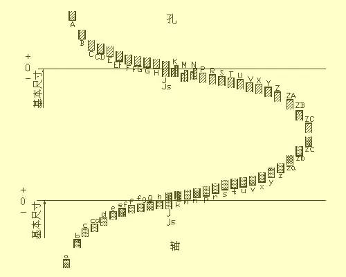
2) Basic deviation
The basic deviation refers to determining the upper or lower deviation of the tolerance zone relative to the neutral position in the standard limits and fits, generally referring to the deviation from the zero line. When the tolerance band is above the zero line, the basic deviation is the lower deviation; otherwise, the upper deviation is. There are 28 basic deviations, the code name is expressed in Latin letters, uppercase is the hole, and lowercase is the axis.
It can be seen from the series of basic deviation series that the basic deviation A~H of the hole and the basic deviation k~zc of the axis are the lower deviation; the basic deviation K~ZC of the hole and the basic deviation a~h of the axis are the upper deviation, JS The tolerance bands of js and js are symmetrically distributed on both sides of the zero line, and the upper and lower deviations of the holes and the axes are +IT/2 and -IT/2, respectively. The basic deviation series only shows the position of the tolerance band and does not indicate the tolerance. Therefore, one end of the tolerance band is an opening and the other end of the opening is defined by a standard tolerance.
Basic deviations and standard tolerances, according to the definition of dimensional tolerances, have the following calculations:
ES=EI+IT or EI=ES-IT
Ei=es-IT or es=ei+ITThe tolerance band code for the hole and the shaft is composed of the basic deviation code and the tolerance band level code.
6, with
The relationship between the mutually identical holes and the shaft tolerance band of the same basic dimensions is called a fit. According to the different requirements of use, the fit between the hole and the shaft is loose and tight, so the national standard specifies the type of cooperation:
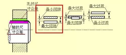
1) clearance fit
When the hole is assembled with the shaft, there is a fit of the gap (including the minimum clearance equal to zero). The tolerance of the hole is above the tolerance band of the shaft.
2) Transitional cooperation
When the hole is assembled with the shaft, there may be a gap or interference fit. The tolerance band of the hole overlaps the tolerance band of the shaft.
3) interference fit
There is a fit between the hole and the shaft when it is assembled (including the minimum interference equal to zero). The tolerance of the hole is below the tolerance band of the shaft.
基准 Benchmark system
When manufacturing a mating part, one of the parts is used as a reference part, and its basic deviation is constant. A system for obtaining various combinations of properties by changing the basic deviation of another non-reference part is called a reference system. According to the actual needs of production, the national standard specifies two benchmark systems.
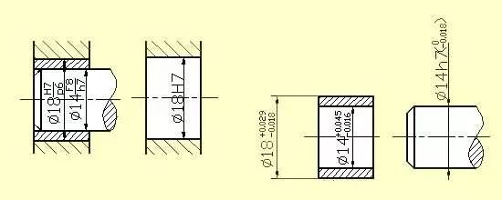
1) Base hole system (as shown in the lower left figure)Base hole system - refers to a system in which the tolerance band of a certain basic deviation is a tolerance band of a shaft with different basic deviations. See the picture below left. The hole made by the base hole is called the reference hole, and its basic deviation code is H, and its lower deviation is zero.
2) Base shaft system (as shown in the lower right figure)
Base shaft system - refers to a system in which the basic deviation is a certain tolerance band of the shaft and the tolerance band of the hole with different basic deviation forms various cooperation. See the picture below right. The axis of the base shaft is called the reference axis, and its basic deviation code is h, and the deviation is zero.

é…åˆ Match code
The matching code consists of the tolerance band code of the hole and the shaft, writes the component number form, the numerator is the tolerance band code of the hole, and the denominator is the tolerance band code of the axis. Any element containing H in the molecule is a base hole, and the denominator contains h in the base axis.
For example, 1: φ25H7/g6 means that the basic size of the fit is φ25, the clearance fit of the base hole, the tolerance band of the reference hole is H7, (the basic deviation is H tolerance level is 7), and the tolerance band of the shaft is G6 (basic deviation is g, tolerance class is 6).
For example, 2: φ25N7/h6 means that the basic dimension of the fit is φ25, the base shaft is made of a transition fit, the tolerance band of the reference axis is h6, (the basic deviation is h, the tolerance grade is 6), and the tolerance band of the hole is N7 (basic deviation is N, tolerance level is 7).
公差 Tolerance and labeling on the pattern
1) Mark tolerances and fits on the assembly drawing, using combined notation.2) There are three forms of labeling methods on the part drawing.
7, geometric tolerance
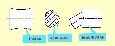
After the parts are machined, there are not only dimensional errors, but also geometric and mutual position errors. Cylindrical bodies, even when the size is qualified, may have a large end, the other end is small or the middle end is thick, and the cross section may also be out of round, which is a shape error. Stepped shaft, after machining, different axes of each shaft segment may occur, which is a positional error. Therefore, the shape tolerance refers to the allowable variation of the actual shape to the ideal shape. The position tolerance is the allowable variation of the actual position to the ideal position. The two are referred to as geometric tolerances.
Geometric tolerance bullet
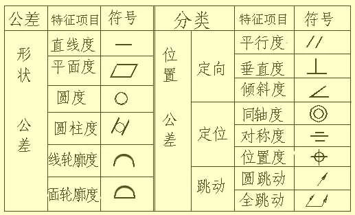
Geometric tolerances â– Codes for shape and position tolerances
The national standard GB/T 1182-1996 specifies the use of codes to mark the shape and position tolerances. In actual production, when the geometric tolerance cannot be marked with a code, it is allowed to use textual description in the technical requirements.
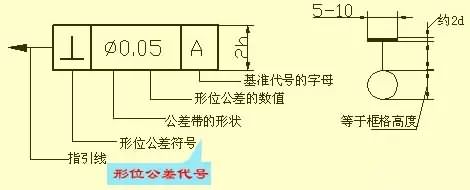
Geometric tolerance codes include: symbols for geometric tolerances, geometric tolerance grids and guides, geometric tolerance values ​​and other related symbols, and reference codes. The height h of the font in the sash is the same as the size number in the drawing.
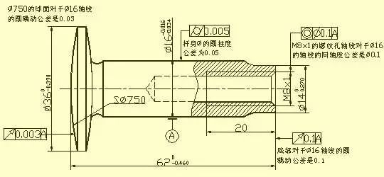
å½¢ Example of geometric tolerance labeling
A valve stem, the text added near the geometric tolerances marked in the figure, is simply written for the reader's explanation, and no repeated writing is required in the actual pattern.
Optional length :
50cm ,100cm,200cm ,300cm
Certificate :
TUV,ENEC ,UL
3 wires 2 circult track lighting systems
Extruded aluminum profile
High performance at thermal conductivity
Surface finished with powder coating
White &black color are available .
Varied types of connectors are available
3pcs of copper strips for electrical conductivity.
The copper strips conduct well at power supply
Flame retarded PVC strips ensure electrical safety
Accessories are available for suspended mounting.
thicken LED Three Wires two circults Track Rail with UL certificates
Farwise Technology Co.,Ltd. , https://www.farwiselighting.com