Photovoltaic Lifting Project Technical Specification (SL 540-2011)
1 General
1.0.1 In order to improve the construction and management level of the photovoltaic water lifting project and standardize the design, installation, construction, acceptance and management of the photovoltaic water lifting project, this standard is formulated.
1.0.2 This standard is applicable to the design, installation, acceptance, and management of photovoltaic water lifting projects with unit power less than 100kW.
1.0.3 The standards cited in this standard mainly include:
"Measurement of pump flow rate" (GB/T 3214-2007)
Surface Water Environmental Quality Standard (GB 3838-2002)
"Design and Identification of Crystalline Silicon Photovoltaic Modules for Ground Use" (GB/T 9535-1998)
"Submersible Pump Test Method" (GB/T 12785-2002)
Groundwater Quality Standard (GB/T 14848-93)
"Design Code for Foundation of Building" (GB 50007-2002)
"Code for Seismic Design of Buildings" (GB 50011-2001)
"Code for Design of Steel Structures" (GB 50017-2003)
"Lightning Protection Design Specifications for Buildings" (GB 50057-2010)
"Code for acceptance of construction quality of steel structures" (GB 50205-2001)
"Code for Construction and Acceptance of Water Supply and Drainage Pipelines" (GB 50268-2008)
Unified Standard for Acceptance of Construction Quality of Building Engineering (GB 5030-2001)
Technical Regulations for Wind Lifting Engineering (SL 343-2006)
1.0.4 In addition to the provisions of this standard, the photovoltaic water lifting project shall comply with the relevant national standards.
2 Terms
2.0.1 Photovoltaic pumping system photovoltaic (PV) pumping system
A device that converts solar energy into electrical water.
2.0.2 special water pump for PV pumping system
Water pump for photovoltaic systems.
2.0.3 controller controller
It mainly completes the equipments with functions such as maximum power tracking control, start-up and stop control of photovoltaic water lifting, and inverter control.
2.0.4 total water output annual water output
Under the rated head, the sum of the total amount of water extracted by the photovoltaic water collection unit in one year under different solar radiation conditions. The estimation assumes that the equipment availability is 100%.
2.0.5 Photovoltaic array rated voltage
Under the specified working conditions, the output voltage is selected according to the characteristics of the same type of solar cell module, so that the output power of this type of solar cell module is close to the maximum power, and this voltage is called the rated voltage.
2.0.6 Photovoltaic array rated power
The rated output power of the solar array at a rated voltage under rated operating conditions.
2.0.7 peak power
The solar cell module square, rated maximum output power under standard test conditions.
2.0.8 Total solar radiation throughout the year
The amount of total solar radiation received by a designated area within a year is usually expressed as: kW·h/(m2·a) or MJ/(m2·a).
2.0.9 Annual Sunshine Hours annual sunshine hours
For a period of one year, the sum of the time when the intensity of the radiation perpendicular to its plane of rays is not less than 120 W/m2, in hours.
2.0.10 Annual variation of solar radiation annual variation of solar radiation
Within a year, the monthly mean solar radiation changes from January to December.
2.0.11 Annual variation in solar radiation daily variation of solar radia-tion within a year
Daily changes in the base of the daily change in the amount of solar radiation are the annual average of the average daily solar radiation at one and the same time in a year, and the change in the amount of solar radiation in 24 hours.
2.0.12 Monthly solar radiation changes daily variation of solar radia-tion monthly
The daily change in the daily base, and the daily change in the amount of solar radiation in each month, is the monthly mean value of the average daily solar radiation at one and the same time in a month, and the change in the amount of solar radiation in 24 hours.
2.0.13 Double axle tracking support double axle tracking support
A two-dimensional rotating photovoltaic array support that automatically tracks the orientation and height of the sun.
2.0.14 Single axle tracking support single axle tracking support
One-dimensional rotation of the photovoltaic array support that automatically tracks the orientation of the sun.
2.0.15 Fixed bracket fixed support
Photovoltaic phalanx stands that are fixed at the designed azimuth and elevation angles do not have the function of automatic tracking.
2.0.16 support foundation
Ground structure used to hold the photovoltaic array support.
2.0.17 Photovoltaic array
A power generation unit that is composed of several solar cell modules together with a supporting structure.
2.0.18 array dip array dip
The angle between the inclined surface of the solar cell module and the horizontal plane.
2.0.19 solar elevation angle solar elevation angle
The angle between the line connecting the sun's rays and the observation point and the horizontal plane.
2.0.20 Solar declination angle
The angle between the center line of the day and the center of the equatorial plane.
2.0.21 solar azimuth
The angle between the projection of Earth's observation point and the center of the sun on the ground, and the angle between it and the south direction.
2.0.22 total lift of photovoltaic pumping station
When the amount of water pumped by the PV lifter system is between 9:00 and 17:00 during the summer and between 10:00 and 15:00 during the winter, the amount of water moved by the water source to the center of the inlet of the reservoir is balanced. The sum of the height difference and the resistance of the water pipeline.
3 Composition and Classification of Photovoltaic Pumping Works
3.1 The composition of the project
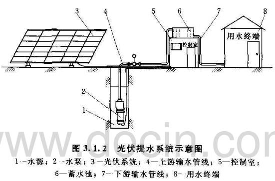
3.1.1 The photovoltaic water lifting project shall consist of the following components: photovoltaic panels, supports, foundations, battery packs (if any), control systems, pumps for photovoltaic water extraction, water intake buildings, water transmission pipelines, reservoirs (if any ), water terminals, safety nets, etc.
3.1.2 Photovoltaic pumping system See Figure 3.1.2.
3.2 Model and Classification of Photovoltaic Pumping Units
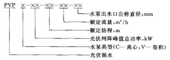
3.2.1 The model of the PV water-lifting unit should consist of the following parts
3.2.2 Photovoltaic pumping units should be classified according to the following methods:
1 According to the power transmission route, it should be divided into the following two categories:
1) The water pumping unit directly driven by the photovoltaic array.
2) Storage battery (group) water storage pump unit.
2 According to the current form of the water pump drive motor, it should be divided into the following two categories:
1) The water pumping unit of the photovoltaic pump driven by a DC motor.
2) The water pumping unit of the photovoltaic pump driven by the AC motor.
3 According to the working principle of the pump, it should be divided into the following two categories:
1) Centrifugal pump water extraction, including ordinary centrifugal pumps and special centrifugal pumps.
2) Pump for volumetric pumping, including piston pumps, Screw pumps and other pumps.
4 Photovoltaic pumping water project design
4.1 Construction Conditions
4.1.1 There should be stable and reliable solar energy resources: The sunshine hours for the whole year should not be less than 2200 hours; the annual total solar radiation should not be less than 1000 kW·h/(m2·a).
4.1.2 The minimum temperature for unit survival shall be -40°C, and the maximum temperature limit shall be +60°C.
4.1.3 The maximum wind speed in 50 years shall not exceed 50m/s.
4.1.4 The water source conditions shall meet the requirements of section 4.3.
4.2 Solar Energy Analysis
4.2.1 The selection of a weather station for reference should meet the following requirements:
1 The altitude of the certified weather station should be similar to the altitude of the construction site, and the elevation difference should not be more than 200m.
2 The latitude of the certified weather station should be similar to the latitude of the construction site, and the latitude difference should not be greater than 0.5o.
3 The reference weather station should be the nearest weather station to the construction site, and the straight-line distance should not exceed 100km.
4.2.2 When collecting solar energy resources, the basic data collected at the weather station should include the following contents;
1 Station type and measurement standard.
2 The total amount of solar radiation over the calendar year and the average monthly solar radiation.
3 Monthly average temperature for 10 consecutive years.
4 Maximum continuous sunshine hours.
5 The number of sunshine hours for the consecutive 10 years.
6 Other meteorological data: Meteorological data such as atmospheric pressure data, extreme temperatures, annual number of thunderstorm days, sandstorm days, snow depth, and frozen soil depth recorded at the station.
4.2.3 The actual survey data of the construction site should include the following contents:
1 Total solar radiation, direct radiation, and scattering amount for each successive year.
2 consecutive year-by-year temperature.
3 Collect parameters related to the declination angle, time angle, solar elevation angle, and sun azimuth.
4.2.4 The assessment of solar resource data should adopt the following methods:
1 The data of solar energy resources should be measured for at least one year for the construction site of the project, obtain the corresponding period data of the corresponding weather station, correct it as a set of representative data reflecting the long-term average level of the PV array, and then Data for resource assessment.
2 There is no measured solar resource data in the construction site, which can be evaluated by using the solar resource data of the corresponding representative weather station.
4.2.5 The assessment of solar energy resources should include the following:
1 total annual solar radiation.
2 The annual change of solar radiation and the daily change of solar radiation throughout the year (compared with the curve of annual change of solar radiation and the annual change of load over the same period; the daily change curve of solar radiation is compared with the daily change curve of the load during the same period.) The more consistent or close the better.)
(3) The daily change of the amount of solar radiation in each month (compared with the daily change curve of solar radiation in each month and the daily change curve of load in the same period, the more the two are consistent or close to each other), the better.
4 The annual maximum daily radiation.
5 Minimum annual daily radiation.
6 sunshine hours throughout the year.
4.3 Water Analysis
4.3.1 Photovoltaic pumping water sources should meet the following requirements:
1 Before the selection of water sources, the investigation and evaluation of water resources should be conducted.
2 Water intake buildings should be simple and reliable. When surface water is used as a source of water, small reservoirs, reservoirs, river bank water intake facilities, and water cellars can be constructed; when groundwater is used as the source of water, large wells, wells, and intercepted flow (infiltration) can be used.
3 The photovoltaic water-lifting unit should be close to the water source project. The distance between the water-lifting unit less than 2 kW and the water source should not exceed 10 m, and the distance between the water-lifting unit not less than 2 kW and the water source should not exceed 20 m.
4.3.2 The water quality of the photovoltaic water lifting project should meet the following requirements
1 The source water of the photovoltaic water lifting project should be clean water, such as river water, lake water, pond water and well water. The temperature of the water should not exceed 40°C.
2 For groundwater sources, to extract the main drinking water, the source of water should be selected from the groundwater of Classes I to III specified in GB/T 14848-93; the water used for industrial, agricultural, and animal husbandry production, the water source can be selected from GB/T. Type I-V groundwater specified in 14848-93.
3 For surface water sources, the main source of drinking water for drinking water, the source of water should be selected from Class I to Class III surface water specified in GB 3838-2002; mainly industrial, agricultural, and livestock production water, the water source can be selected from GB 3838-2002 Class I to V surface water specified.
4.3.3 The amount of source water for photovoltaic water lifting project shall meet the following requirements:
1 When using groundwater sources, the allowable extraction volume should be greater than the water withdrawal volume.
2 When using surface water sources, the annual guaranteed rate of dry flow design should not be lower than 90%.
3 When the amount of water from a single source cannot meet the requirements, measures such as multiple sources or storage of water can be used.
4 The depth of movement of water wells shall not exceed 2m.
5 The water supply capacity of the water source should be greater than the flow rate of the water pump.
4.4 Engineering Design
4.4.1 The design of photovoltaic water lifting project shall meet the following basic requirements;
1 There should be no sun shading obstacles affecting photovoltaic power generation around the photovoltaic pumping station.
2 The water supply reservoir shall have gravity water supply conditions and shall have a certain volume. When the reservoir is full, it shall ensure that the water supply can still be provided normally when the pump station cannot carry water for 3 consecutive days. Reservoirs should not be built near garbage sites and livestock drinking areas.
3 The space required for other water dispensers should be reserved at the pumping station.
4 The system should have a water release device.
5 Safety protection facilities or warning signs should be provided at the photovoltaic arrays, water sources, and reservoirs.
6 The water transmission pipeline should not have large ups and downs, and appropriate technical measures should be adopted when crossing the bad geological and geographical areas. There should be no obvious leakage at the water pipeline interface.
4.4.2 The photovoltaic water lifting project shall meet the following technical requirements:
1 The photovoltaic water pumping unit should be able to work normally at -20 ~ +60 °C.
2 In the area where PV modules are installed, the foundation should have corresponding bearing capacity to avoid swamps, mudflats, and sand drift. Geological conditions should meet the requirements of GB 50007-2002.
3 The battery array and the control room should be close to the water source, and the distance should not exceed 20m.
4 The water flow rate in the water pipe should be 0.6 to 2.0 m/s.
5 The volume of the reservoir should not be less than 3 times of the maximum daily water consumption; the head of the lowest point of the reservoir should be 2m higher than the head of the most unfavorable water terminal.
6 The controller of the photovoltaic lift pump station with more than 2kW should have electronic automatic protection functions such as undervoltage and overload.
7 There should be energy dissipation and anti-scouring devices at the water outlet of the pumping station.
8 In the photovoltaic pump station for winter operations, the water transmission pipelines shall be buried below the frozen layer, or other corresponding anti-freeze measures shall be taken. Valves shall be installed at the valves on the pipelines.
4.5 Unit Selection
4.5.1 Unit type selection should consider the following factors:
1 Engineering use.
2 Solar resource conditions.
3 Lifting water flow and lift.
4.5.2 Unit type selection should meet the following requirements:
1 The water pumping unit with a flow rate of not less than 10m3/h and a lift of not more than 30m should preferably use a centrifugal pump water pumping unit.
2 For water lifting units with a flow rate of less than 10m3/h and a lift of more than 30m, a high-lift, low-volume positive displacement pumping unit shall be used.
3 The large amount of sediment in the water should be chosen centrifugal pump water pump unit.
4.6 Determination of Related Parameters of Photovoltaic Pump Stations
4.6.1 The daily water requirement in the water supply area shall meet the requirements of Article 6.3.2 of SL 343-2006.
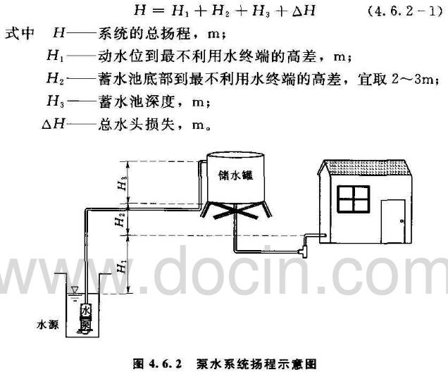
4.6.2 The determination of the total head of the PV pumping station shall be carried out in the following manner:
1 The total head of the PV pumping station should be calculated according to formula (4.6.2-1). The height difference between H1, H2 and H3 is shown in Figure 4.6.2.
2 Total head loss should be calculated according to formula (4.6.2-2):
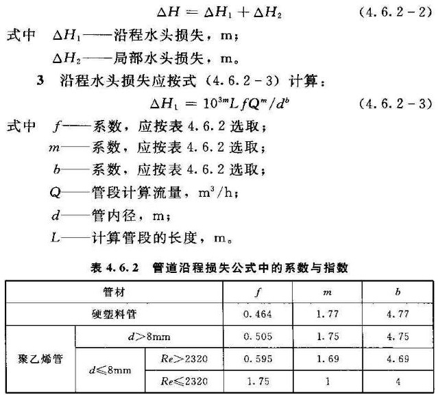
4 The local loss of water delivery pipes and water distribution pipes can be calculated as 5% to 10% of the head loss along the waterway; the local head loss of the water distribution pipe and the pipes below it can be calculated as 10% to 20% of the head loss along the way.
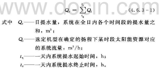
4.6.3 The determination of the pumping system flow rate should be carried out in the following manner:
The amount of water lifted on the 1st should be calculated according to formula (4.6.3-1):
2 The photovoltaic water collection system shall calculate the maximum daily water supply guarantee rate for the entire year, the minimum daily solar water supply guarantee rate and the annual water supply guarantee rate respectively, or determine the water supply guarantee rate according to the actual needs of users.
1) The maximum daily water supply guarantee rate for the whole year should be calculated according to formula (4.6.3-2):
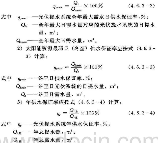
3 In the construction of photovoltaic pumping stations, the water supply guarantee rate of photovoltaic pumping stations should first meet the requirements of the annual water supply guarantee rate.
4.7 Determination of PV array capacity
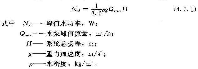
4.7.1 The maximum peak water power of the PV array shall be calculated according to formula (4.7.1):
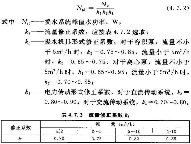
4.7.2 Photovoltaic pumping system The peak power of the pump shall be calculated according to formula (4.7.2):
4.7.3 The capacity of the PV array shall be calculated according to formula (4.7.3):
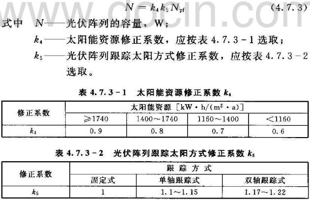
4.8 PV array design
4.8.1 The determination of the azimuth and optimal inclination of the PV array shall be carried out in the following manner:
1 The optimum inclination angle of the fixed-stent photovoltaic array is selected with reference to the optimum inclination angle in Table A of Appendix A.
2 For the calculation of the azimuth and optimal inclination of the tracking frame PV array, see Appendix B.
1) Single-axis tracking support system: With the optimal tilt angle of the fixed photovoltaic array, the azimuth angle is changed along with the change of the position of the solar track, and the total amount of solar radiation it receives is calculated.
2) Two-axis tracking support system: change the azimuth angle and inclination angle as the position of the sun's trajectory changes, and calculate the total amount of solar radiation it receives.
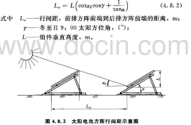
4.8.2 The spacing of PV arrays should be calculated according to formula (4.8.2). The schematic diagram of the spacing between solar arrays is shown in Figure 4.8.2.
4.8.3 The structure of the PV array mounting bracket should be designed according to the method:
1 The installation of photovoltaic panels should be fixed under the bolt back plate and fixed on the bracket frame. The bolts and nuts are galvanized.
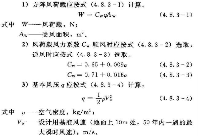
2 The design of photovoltaic panels fixed brackets should not be less than the wind speed of the local gust, and the square wind load and the basic wind pressure should be calculated.
The deformation of the carbon steel support structure system shall meet the requirements of GB 50017-2003 and GB 50205-2001.
4 The seismic rating of the support system refers to the requirements specified in GB 50011-2001 Class C Building.
5 The connection of the bracket and the embedded part of the bracket base adopts the form of welding (or bolting), and the anti-corrosion treatment should be done after the installation is completed.
4.9 Water Storage Engineering Design
4.9.1 The form of the storage project should be determined by the geology, topography, use and economic conditions of the construction site. It is advisable to use water tanks, pools and cellars. The project should meet the requirements of small leakage, safe water storage and a certain useful life. Impervious projects in the impoundment of water storage projects, structural forms, structural dimensions and supporting facilities shall be designed in accordance with the design requirements, so as to be safe, simple and applicable, and local materials should be adopted to reduce the project cost.
4.9.2 In addition to the provisions of Section 4.4, the storage engineering design shall meet the following requirements:
1 The impounding project shall be treated with anti-seepage treatment, and corresponding impervious materials and engineering measures shall be adopted in accordance with the different types of impoundment projects and soil conditions.
2 The structure and size of the water storage project shall meet the principles of safety and stability, economical rationality and ease of use.
(3) Roofs should be built for water storage projects built for domestic water or semi-arid areas. Reservoirs in cold areas should adopt insulation measures
(4) Trash racks should be installed before the inlet of water storage projects. If necessary, a sand basin should be built before the water inlets. Water outlets of water storage projects should be equipped with water shutoff facilities and drainage channels should be provided. Drains should be provided for normal water storage projects. (Port); The bottom outlet pipe or inverted siphon inlet of the storage project should be 30cm higher than the bottom plate.
5 The height difference between the water project and the water source should be matched with the design lift of the PV water-lifting unit and should not be larger than the design lift of the PV water-lifting unit.
6 The reservoir should not be susceptible to rain erosion and pollution.
4.9.3 The design of water cellars and pools shall comply with the requirements of Clauses 6.4.3 and 6.4.4 of SL 343-2006.
4.10 Water Distribution Engineering Design
4.10.1 The layout of water transmission lines, water pipelines, water distribution pipelines, and arrangements shall comply with the requirements of Section 6.5 of SL 343-2006.
4.10.2 The flow rate of the water distribution pipe network should adopt the economic flow rate as the design flow rate; when the outlet pipe diameter is less than 250 mm, the design flow rate should be 1.0 to 1.2 m/s; when the outlet pipe diameter is not less than 250 mm, the design flow rate should be 1.5 to 2.0 m/s. The economic flow velocity of the gravity flow water transmission pipeline should be fully determined by the terrain height difference, and the design flow velocity of the long-distance gravity flow water transmission pipeline should not be greater than 1m/s.
4.11 system lightning protection design
4.11.1 Lightning protection should be required when the system has the following conditions:
(1) Lightning protection system should be installed when it is installed in the open field or in the periphery of the building and beyond the height of the building.
2 Small pumping stations less than 10 kW and low voltage transmission lines should only consider the prevention of lightning and lightning wave intrusion.
4.11.2 System lightning protection design The lightning protection rating of the third category of lightning protection structures in GB 50057-2010 shall be adopted.
4.11.3 The system shall take the following lightning protection measures:
1 The metal shielding layer of the solar cell array and control room equipment, metal objects and cables shall be reliably grounded; each device shall be grounded separately, and shall not be connected to the grounding trunk after being connected in series; the grounding resistance shall not exceed 10Ω; Each side of the input should be equipped with lightning protection module to prevent lightning.
2 For the low voltage 220V/380V, low-voltage valve arresters shall be installed on the outgoing line and the zero line of each circuit to prevent the intrusion of lightning waves.
3 For photovoltaic pump stations with a capacity of not less than 10 kW, lightning rods shall be erected within 5 m of the pump station to prevent direct lightning strikes.
4.12 system energy-saving design
4.12.1 The system shall be arranged centrally and access to the power distribution room nearby.
4.12.2 Reasonable supply voltage and power supply mode should be selected.
4.12.3 Energy-saving electromechanical equipment and materials with advanced technology, reliable performance, excellent materials, reasonable structure, stable operation, high mechanical strength, and long service life should be selected.
5 PV water lifting project installation and construction
5.1 General provisions
5.1.1 The construction plan, schedule, organization measures and step-by-step quality acceptance plan shall be prepared before the construction of the photovoltaic water lifting project. After both the owner and the builder jointly approve the signing of the contract, they can be put into construction.
5.1.2 Construction shall be carried out according to design drawings and technical requirements. If any changes are required, the consent of the owner and the original designer shall be obtained.
5.1.3 During the construction process, construction records should be made
5.2 Civil Engineering
5.2.1 After determining the location of the installation of photovoltaic arrays, earthworks for excavation pits, water intake building pools and water transmission lines shall be excavated according to design requirements.
5.2.2 After the foundation pit is excavated, a 200mm gravel cushion shall be subdivided and then a 50mm plain concrete cushion shall be poured. After the concrete of the bedding layer is solidified, the steel reinforcement shall be placed or the foundation embedded parts shall be placed and the foundation concrete shall be poured.
5.2.3 In the backfill of pit foundations in cold areas, non-frost bulk materials such as coarse sand and medium sand may be backfilled on the sides of the foundation.
5.2.4 The anchor bolts and embedded parts shall be removed from floating rust before installation, and the threads shall be coated with butter. The installation shall be firm and accurate.
5.2.5 Water intake for surface water The construction and diversion should be done well during the construction of buildings. The safety of the existing bank protection and dam slopes should not be affected.
5.2.6 The foundation reinforced concrete shall not be lower than C30, and concrete pouring shall be started after 12 hours of concrete pouring, and the concrete drying time in hot dry and windy weather shall be 3 hours.
5.3 unit installation
5.3.1 Unit installation shall be carried out according to the following regulations:
1 The installer should inspect the site before installation and list the installation tools and materials in detail.
2 The installation staff should be composed of qualified personnel.
3 The installer should know in advance the risks that may occur during the installation.
4 After the photovoltaic water lifting equipment is shipped to the site, the installer should count the quantity according to the packing list, check the certificate and keep a record list. At the same time, read the instructions carefully to understand and be familiar with the characteristics of the installed equipment, and to master the installation procedures and methods. .
5.3.2 The installation of components shall be carried out as follows:
1 The same configured components should be used in the same photovoltaic power generation system.
2 The installation should first measure the open circuit voltage and short-circuit current of the solar module.
3 Apply opaque material completely to cover the assembly during installation.
4 The components should be fixed to the bracket using four symmetrical mounting holes on the inside of the frame. Reinforce measures can be designed in areas with strong wind and heavy snow.
5 Do not step on the assembly when installing, and avoid dropping the assembly or letting objects fall on the assembly.
6 The back of the module should be well ventilated during installation (the minimum distance between the assembly and the mounting surface should be 10cm).
7 Photovoltaic array installation height from the ground should not be less than 50cm.
8 The location of the components should be chosen in accordance with the requirements of various electrical and fire protection standards.
5.3.3 Bracket installation should be carried out according to the following regulations:
1 The bracket structure should be made of durable, rust-proof and UV-resistant material.
2 The bracket parts directly installed on the concrete base shall be made of galvanized material. The screws, nuts and gaskets shall be made of galvanized material.
3 The firmness of the bracket should be able to withstand the constant load, wind, snow, earthquake pressure, and other external forces.
5.3.4 Controller installation shall be carried out according to the following regulations:
1 The controller should be visually inspected before installation. The appearance should not be damaged, and the internal cables and screws should not be loosened.
When installing the controller, connect the battery (group), connect the input of the solar module, and finally connect the load or inverter.
3 The wiring should distinguish the enthusiasm of the government and ensure the connection is firm.
4 If the photovoltaic controller needs to be installed outdoors, it should be put into the box and it should meet the moisture-proof requirements of the seal.
5 Controller installation location should be well ventilated.
5.3.5 Electrical installation shall be carried out as follows:
1 Electrical installations should use approved safety equipment (insulated tools, insulated gloves, etc.).
2 All the wiring of the PV system should be transferred from the nearest electrical junction box.
3 Use equipment, connectors, wires, and mounting equipment suitable for photovoltaic systems.
4 The cross-sectional area and connector capacity of the cable selected by the system shall meet the requirements of the maximum system short-circuit current.
5 The components and component brackets should be properly grounded. The grounding wire should be connected with the bolts and pressed with pressure clamps.
5.3.6 The pump installation should be carried out according to the following regulations:
1 The actual suction stroke of the pump should be lower than the allowable suction stroke of the pump.
2 The water inlet pipe of the pump should be short and straight, and should not protrude upward or above the water pump in the horizontal line.
3 The outlet pipe of the water pump should be enlarged and should be close to the surface of the water, and a larger pipe diameter should be taken for long distance transmission. The piping of the pump should have a special bracket, and the weight of the pipeline should not be added to the pump.
4 The distance from the bottom of the water source and the edge of the water source at the bottom valve of the water pump or the inlet pipe should not be less than the diameter of the inlet pipe, and the depth of the water inlet pipe should not be less than 0.5m.
5 discharge line check valve should be installed outside the valve, pump lift should be installed more than 20m check valve.
5.3.7 After installation of each link, professionals shall be sent to conduct inspections of equipment and works under the supervision of the owner's representative and make records.
5.4 unit commissioning
5.4.1 Unit commissioning should be carried out in clear weather. It should be implemented according to the manufacturer's recommended method.
5.4.2 The intensity and output voltage and current of the sun shall be measured and compared with the manufacturer's instructions to judge the operational status of the phalanx.
5.4.3 The correctness of each branch wiring should be reviewed to confirm the correctness of the positive and negative DC loops.
5.4.4 Verify that the positive and negative polarities of the controller wiring are correct, check and confirm that the AC output voltage is correct, connect the pump to lift the water, and the components should work normally.
5.4.5 The operation status of the photovoltaic water collection system shall be fully debugged and the starting working point and rated working point shall be checked.
5.4.6 Various protection functions such as undervoltage and overload should be tested.
5.4.7 The operation status of the photovoltaic water collection system shall be fully tested and the main operating parameters of each part of the system shall be recorded and compared with the product specification.
5.4.8 The unit shall be operated after being qualified by the professional commissioning.
5.4.9 If the debugging does not meet the design requirements, contact the design unit or the manufacturer.
6 Acceptance of PV water lifting project
6.1 Unit Performance Testing
6.1.1 Unit performance testing should include the following parameters:
1 Irradiation intensity.
2 PV module performance parameters.
3 traffic.
4 head.
5 Unit output characteristics.
6 efficiency.
6.1.2 The testing equipment should meet the following requirements:
1 The unit performance testing equipment shall include three types of testing instruments: solar radiation measurement, electrical parameter measurement, and hydraulic characteristics measurement.
2 The accuracy of the testing instrument should not exceed 1.5.
3 Testing instruments, meters and tools should be within the validation period.
4 Select the instrument so that the measured value is within 40% to 70% of the instrument's measuring range.
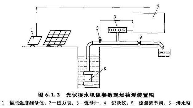
5 The parameters of the on-site detection device for PV water pumping unit are shown in Figure 6.1.2.
6 Flow detection instrument installation location should meet the following requirements:
1) The testing equipment should be located straight along the pipeline.
2) The length of the upstream straight segment of the detection instrument should not be less than 10 times the pipe diameter.
3) The length of the downstream straight section of the testing instrument should not be less than 6 times the pipe diameter.
4) When using the weighing method to measure the flow rate, it shall comply with the provisions of GB/T 12785-2002.
6.1.3 The test conditions should meet the following requirements:
1 The detection of the irradiation intensity by the detection device is relatively stable, and the change can be detected within ±2%.
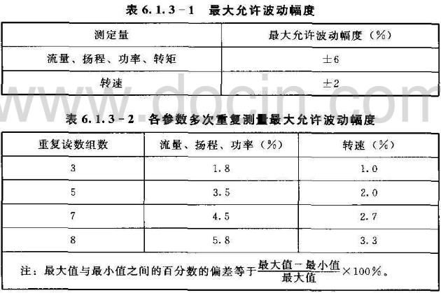
2 When the maximum allowable fluctuation range of the main parameters of the pump and the change value of multiple readings of the same parameter reach the requirements of Table 6.1.3-1 and Table 6.1.3-2, the system is in stable operation. For a set of readings, records should only be made if it is determined that the fluctuations have stabilized within the limits of Table 6.1.3-1 and Table 6.1.3-2.
6.1.4 The test method should meet the following requirements:
1 The measurement of irradiation intensity should make the unit in normal working condition and the irradiation intensity is stable. The radiation intensity detection device should be parallel to the photovoltaic cell array.
2 The detection of photovoltaic module parameters shall be conducted in accordance with the provisions in GB/T 9535-1998.
3 Flow detection should be carried out according to the provisions of GB/T3214-2007.
4 head detection method see Appendix C.
5 The detection method of output characteristics of the unit is shown in Appendix C.
6 The detection method of efficiency is shown in Appendix C.
6.1.5 The test report shall meet the following requirements:
1 After the test is completed, the data collected should be analyzed and a test report written.
2 The test report should include the following main contents:
1) Title.
2) The name and address of the testing organization.
3) The uniqueness of the test report, the page number, and the total number of pages.
4) Test location and date.
5) A clear description of the test method used, or any non-standard method used.
6) Environmental conditions.
7) The description and clear identification of the tested prototype.
8) The equipment used.
9) Detection and export results.
10) The signature, title or equivalent of the person responsible for the content of the test report.
6.2 Detection of Performance of Water Distribution Pipes
6.2.1 Pipeline strength testing shall be carried out in accordance with the method specified in Chapter 10 of CB 50268-2008.
6.2.2 Pipeline tightness shall be tested according to the method specified in Chapter 10 of GB 50268-2008.
6.2.3 Detection of flushing and disinfection of pipelines shall be carried out in accordance with the method specified in Section 10.4 of GB 50268-2008.
6.2.4 The test report for the performance of transmission and distribution pipelines shall be prepared in accordance with 6.1.5.
6.3 Project Acceptance
6.3.1 Civil works such as reservoirs shall be accepted separately according to the provisions of GB 50300-2001.
6.3.2 Acceptance and acceptance of photovoltaic water lifting project shall meet the following conditions:
1 The completion of the acceptance of civil engineering works.
2 The project has been completed and can operate normally as designed.
3 Problems found during trial operation have been processed.
4 Performance testing is complete.
6.3.3 When the project has acceptance conditions, the construction unit shall submit an application report for completion acceptance. If the project fails to meet the deadline for acceptance, the construction unit shall submit a report on the application for acceptance of the deferment due to completion acceptance, including the main reasons for deferring the completion acceptance and the time for the extension of the plan.
6.3.4 Completion acceptance shall be the responsibility of the completion acceptance committee. The Completion Acceptance Committee shall be composed of the representatives of the project acceptance and acceptance units, project management departments, relevant local people’s governments and departments, quality supervision agencies, operation management units, and relevant experts. The committee shall set up one chairman, and if there are one thousand deputy chairman and members, the chairman shall be the representative of the completion and acceptance chairman.
6.3.5 Acceptance basis shall be approved design documents and corresponding design change documents, construction contracts, construction drawings and instructions, equipment technical specifications, relevant national standards and industry standards.
6.3.6 The acceptance of the construction unit should provide technical information for the entire process of construction. It shall include: Feasibility study report and its review opinions for project construction, environmental impact assessment report, design report and design drawing, design change data, construction organization design, bidding information, certification of main materials and equipment, and engineering test data. Intermediate acceptance data, accident handling records, test run data, completion reports, as-built drawings, etc.
6.3.7 Completion acceptance shall include the following main contents:
1 Whether the technical indicators of the photovoltaic water lifting project have reached the contractual requirements.
2 Whether the construction of the photovoltaic water lifting project meets the relevant technical standards.
3 The quality of the photovoltaic water lifting project meets the requirements.
4 The user manual is detailed and whether it can meet the needs of use and maintenance.
6.3.8 Completion Acceptance The meeting shall meet the following procedures:
1 The acceptance committee shall go to the site of the photovoltaic water extraction project for inspection and retest the main parameters.
2 The acceptance committee shall hear the report of the design and construction unit and the trial run report of the owner, review the performance test report of the photovoltaic water lifting unit, the test report of the performance of the transmission and distribution pipelines, and the acceptance report of the civil works.
3 The acceptance committee shall, after necessary questioning and discussion, form a project acceptance report.
4 The report should give a conclusion on whether it is qualified or unqualified, and it should propose corrective opinions on the defects of the project.
5 The member of the acceptance committee and the representative of the accepted organization shall sign the completion acceptance certificate.
6.3.9 When the quality of project acceptance exceeds the above-mentioned levels, and the quality of the project's appearance quality score exceeds 70%, the quality concluding opinion for completion acceptance shall be qualified.
6.3.10 The number of completion acceptance certificates shall be determined according to the composition of the acceptance committee, 1 part of the accepted units, and the number of copies required for archiving. Within 30 working days from the date of adoption, the appraisal book shall be sent to the relevant unit by the receptionist.
7 Operation Management and Maintenance
7.1 General provisions
7.1.1 The management and maintenance personnel shall formulate the operation management system, maintenance plan and specific implementation plan of the photovoltaic water lifting project according to the requirements of management and maintenance.
7.1.2 The maintenance personnel shall perform regular and irregular maintenance and repair of the photovoltaic water lifting project to keep the equipment intact.
7.1.3 The management personnel should be trained on-site according to the system.
7.1.4 The photovoltaic water collection system shall be equipped with various fire protection facilities.
7.2 Managers' Duties
7.2.1 The management personnel shall complete the daily operation and management of the photovoltaic water lifting project, be familiar with the project operation management system and safety regulations, be familiar with the equipment condition and operation and maintenance situation, analyze the condition of the equipment according to the actual operation situation, and master the equipment defects and weak links. Safe operation, correct handling of abnormalities and malfunctions.
7.2.2 The management personnel shall strictly implement the operation duty system, conduct regular inspections of the equipment they control, monitor the changes of the operating parameters of the system equipment, detect the defects and failures of the equipment in time, and take corrective measures for timely processing and recording.
7.3 Project Management and Maintenance
7.3.1 The operation mode of the photovoltaic water lifting project shall be performed in accordance with the requirements of the equipment supplier for the project operation.
7.3.2 Management personnel should focus on inspection and maintenance of the following items
1 The surface of photovoltaic modules should be regularly cleaned; weeds and debris on the ground of photovoltaic arrays should be regularly cleaned to prevent the growth of plants from obstructing sunlight, weeds and sundries, and destroying photovoltaic modules.
2 Periodically check whether the fixing bolts of the bracket, photovoltaic module and lightning protection grounding wire are loose. In particular, check and handle the bolts immediately after strong winds should pass. Check whether the PV module wiring is firm, and if it is found that the looseness should be tightened in time; if there is underground cable, it should be taken. Anti-rat measures.
(3) The static water level and dynamic water level of the water source well should be regularly observed. When the water level and sediment concentration are abnormal, the cause should be identified in a timely manner.
(4) The operation of photovoltaic equipment, water pumps, and control systems should be inspected frequently, and meter readings should be recorded to observe vibration and noise. Water leaks, overburden, and the operation of ancillary facilities of the distribution and distribution pipelines should be inspected and abnormalities should be handled in a timely manner.
5 When the pump is working, the water level of the suction tank should not be lower than the minimum design water level. In addition to the dehumidification submersible pump, the top surface of the remaining submersible pumps should not be more than 2m below the dynamic level.
6 When the ambient temperature is lower than 0°C and the pump is not working, drain the pump's memory.
7.3.3 Equipment failures that have been discovered but cannot be eliminated by management personnel shall be subject to safety measures in accordance with safety regulations. Technical measures shall be taken to prevent accidents and prevent defects and the expansion of failures. The relevant departments shall be promptly notified and the fault records shall be filled in in detail.
7.4 Overhaul of Engineering Equipment
7.4.1 According to the characteristics of the photovoltaic water lifting project, regular preventive maintenance should be adhered to.
7.4.2 Maintenance schedules should be developed and maintained by professionals.
7.4.3 It is preferable to use spare parts or materials supplied by the manufacturer. The management personnel shall be responsible for the management of spare parts, and shall be responsible for the preparation and management of spare parts and drawings and data.
7.4.4 The maintenance and repair technical records of the equipment shall be maintained after each maintenance and inspection.
7.5 Project Archives Management Methods
7.5.1 The file management work of the photovoltaic water lifting project shall be performed by a special person, and the relevant national file management system shall be strictly implemented.
7.5.2工程的技术资料ã€å›¾æ ·ã€ç®¡ç†è§„ç« ã€ç»´æŠ¤æ£€ä¿®è®°å½•ã€å„ç§æ–‡ä»¶ã€è®¾å¤‡æ˜Žç»†ã€æœ‰å…³å„ç§æŠ¥å‘ŠåŠå„ç§è½½ä½“的资料å‡åº”åŠæ—¶ç”±æ¡£æ¡ˆç®¡ç†äººå‘˜æŒ‰æ¡£æ¡ˆç®¡ç†æœ‰å…³è§„定进行建档ã€æ ‡è¯†ã€åˆ†ç±»å’Œç¼–å·
7.5.3管ç†äººå‘˜åº”对归档的档案定期进行整ç†ï¼Œå¯¹è¶…过档案ä¿ç®¡æœŸçš„档案,ç»æ¡£æ¡ˆç®¡ç†äººå‘˜é‰´å®šæ— ä¿å˜ä»·å€¼ï¼Œå¯æŒ‰ç…§å›½å®¶æ¡£æ¡ˆç®¡ç†åˆ¶åº¦é”€æ¯ã€‚
7.5.4对ç»å¸¸ä½¿ç”¨çš„资料ã€è®¾å¤‡è¯´æ˜Žä¹¦ã€å›¾æ ·ï¼Œåº”使用å¤å°ä»¶ï¼ŒåŽŸä»¶åº”å˜æ¡£ã€‚
Kitchen Shelf Organizer,Shelf Organizer,Double layer kitchen shelf organizer,Kitchen shelf organizer racks,Cabinet shelf organizer
Shenzhen Lanejoy Technology Co.,LTD , https://www.szsmallcompressionspring.com