Multi-station progressive die design of terminal block (Figure)
The terminal block shown in Figure 1 is a part of an electrical product. It is made of 1 mm thick cold-rolled steel plate. The production batch is large. It was originally processed in a single process. The process steps are: cutting strips, punching holes, Punching and cutting the bending part, cutting, rounding and bending, a total of five processes, a long cycle, and the need to use four sets of special molds, not only affect the production efficiency of the enterprise and is not conducive to the positioning of parts, dimensional accuracy is not easy to guarantee, In the last compounding process of rounding holes and bending, the former process has been cut into small pieces with a shape of only 20 mm × 12 mm, which causes inconvenience to operation and positioning. In order to meet the production requirements of the enterprise and improve the operating conditions, a multi-station progressive die was designed to meet the above requirements while ensuring the quality of the parts.
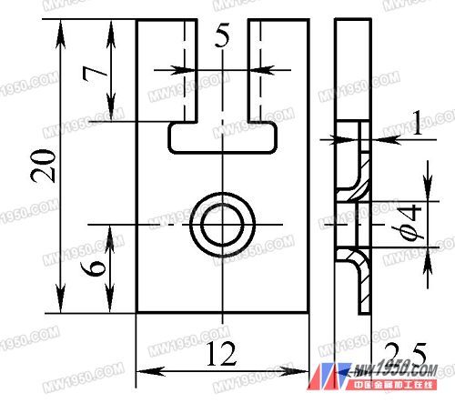
Figure 1 Block structure diagram
Process analysis
The structure of the part is not complicated. It is a forming and bending assembly, and the height of the round hole flanging is not large. After calculation, the height of the flanging after the pre-punching can be formed at one time.
It is noted that the dimensions of the parts are small, the dimensional accuracy of the parts is not high, the production volume is large, and at the same time, considering the processing and manufacturing capabilities of the parts, it is decided to design the multi-station progressive die.
2. Layout design
In order to improve production efficiency and material utilization rate, the entire layout is carried out in a symmetrical arrangement of two parts to design a two-piece mold structure.
The machining of the parts is divided into 5 stations, namely: punching circular holes → punching the middle rectangular holes → prefabricated holes for punching and bending parts → rounding holes and bending → cutting into parts, and the production of two workpieces is completed every press. According to the above analysis, the determined part layout scheme is shown in Figure 2.
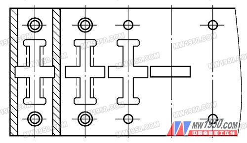
Figure 2 parts layout diagram
3. Mold design
(1) mold structure and working process
According to the part layout drawing, the mold structure shown in Fig. 3 is designed.
Next page
According to the adherence requirements of the product, cells are divided into three categories:
Suitable for suspension culture of common cells and tissues;
The standard type has good cell adhesion performance and is suitable for cell adhesion growth;
Dedicated containing cell pastes (cell clusters that can be used in some special cases, such as cell walls, cell surfaces and secretory cells).
According to the shape of the instrument, it is divided into:
Wide body culture flask;
triangle bottle;
Torticollis flask.
cell culture flask,filter cap cell culture flask,suspension culture flasks,cell tissue culture flask
Yong Yue Medical Technology(Kunshan) Co.,Ltd , https://www.yongyuecellculture.com