Intermittent motion simulation of CATIA
2023-07-15 10:10:58
The sheave mechanism converts the one-way uniform rotation of the drive shaft into a one-way periodic intermittent motion of the driven shaft. FIG. 1 is a radial four-slot sheave mechanism. In a motion cycle, the crank wheel (master shaft) is rotated by 90° per 360° groove (slave axis). It is impossible to use conventional connection and drive definition in DUM_Kinematics. Curve drive is needed to simulate . As shown in Fig. 2, the grooved wheel mechanism is defined by the motion width connection, and the groove wheel and the crank wheel are respectively angularly driven. The sheave drive is "Command.1" and the crank wheel drive is "Command.2".
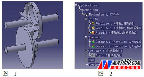
Figure 3 shows the sheave mechanism and related parameters, including: crank wheel angular displacement: ψ1; groove wheel angular displacement: ψ 2;
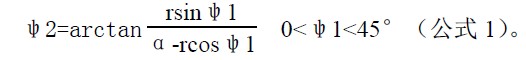
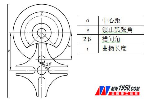
image 3
(1) The angular displacement curve of the groove wheel is established. In the assembly drawing mode, a new Part document is named as “reference curve†(see Fig. 4) for the establishment of the driving curve. Create "law" according to formula 1, named "groove rotation" (see Figure 5).
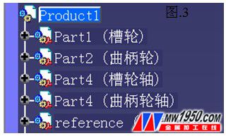
Figure 4
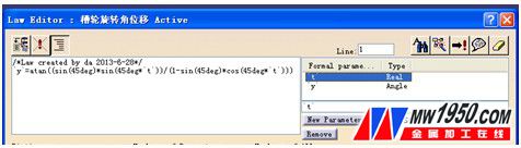
Figure 5
Make a 45mm long straight line, use the "parallel curve" command to offset, the offset distance is controlled by the rule curve "groove angle displacement", generate "curve 1" (see Figure 6), and rotate "curve 1" around the origin At 180°, a “curve 2†is generated (see Figure 7).
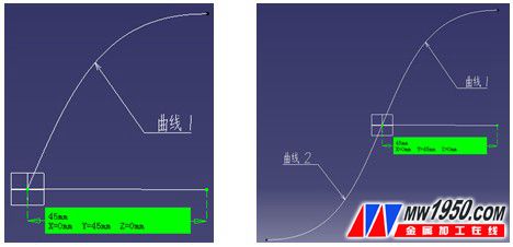
Figure 6 Figure 7
The curve shown in Fig. 8 is combined by "curve 1" and "curve 2", and the "groove motion curve" is established.
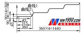
Figure 8
(2) The crank wheel angular displacement curve establishes the crank wheel to make uniform motion, so its angular displacement curve is a diagonal line. In Figure 9, the ordinate indicates angular displacement (degrees), the abscissa indicates time (seconds), and the groove motion The curve is established.
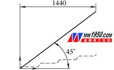
Figure 9
(3) Driver Add Double click "Command.1", pop up "CommandEdition" dialog box, click "Link" to pop up "SketchSelectionforCommand.1" dialog box, fill in "Maximumtimevalue" with time "1440" and then select "groove angle" Displacement curve" sketch. The same method is used to assign "Command.2", and all the work is completed, and the simulation is performed with "SimulationWithLaws" (see Figure 10).
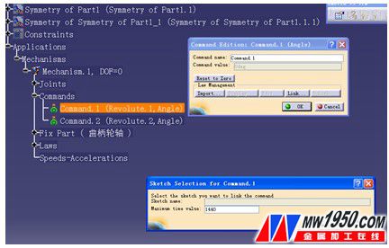
Figure 10
After confirming the simulation generated by this method, the transmission accuracy is very accurate. By using the curve driver flexibly in CATIA, more motion simulations can be realized without having to import it into professional software, which also improves the efficiency of our modification and structural optimization of parts.
Plastic Headlight,Polishing Plastic Headlights,Car Plastic Headlight,Defog Plastic Headlights
NINGBO ZHENGUO INTELLINGENT LIGHTING CO.,LTD , https://www.zguolight.com